
PPT Digital Image Processing PowerPoint Presentation, free download
A band-reject filter rejects frequencies between the lower limit fL f L and the higher limit fH f H, and passes other frequencies. As for the band-pass filter, you can get this result in two steps. In the first step, you apply a low-pass filter with cutoff frequency fL f L, xlpf,L[n] = x[n] ∗hlpf,L[n], x l p f, L [ n] = x [ n] ∗ h l p f, L [ n],
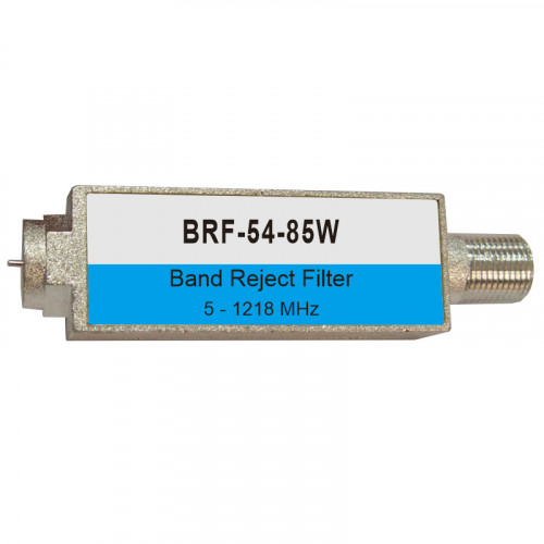
BRF5485W Band Reject Filter
Band-reject filters are the inverse of a bandpass filter: they filter out unwanted power within a specific frequency range. The transfer function of a band-reject filter can be calculated by hand or using a SPICE simulator. Anyone who has played an analog synthesizer probably understands filters
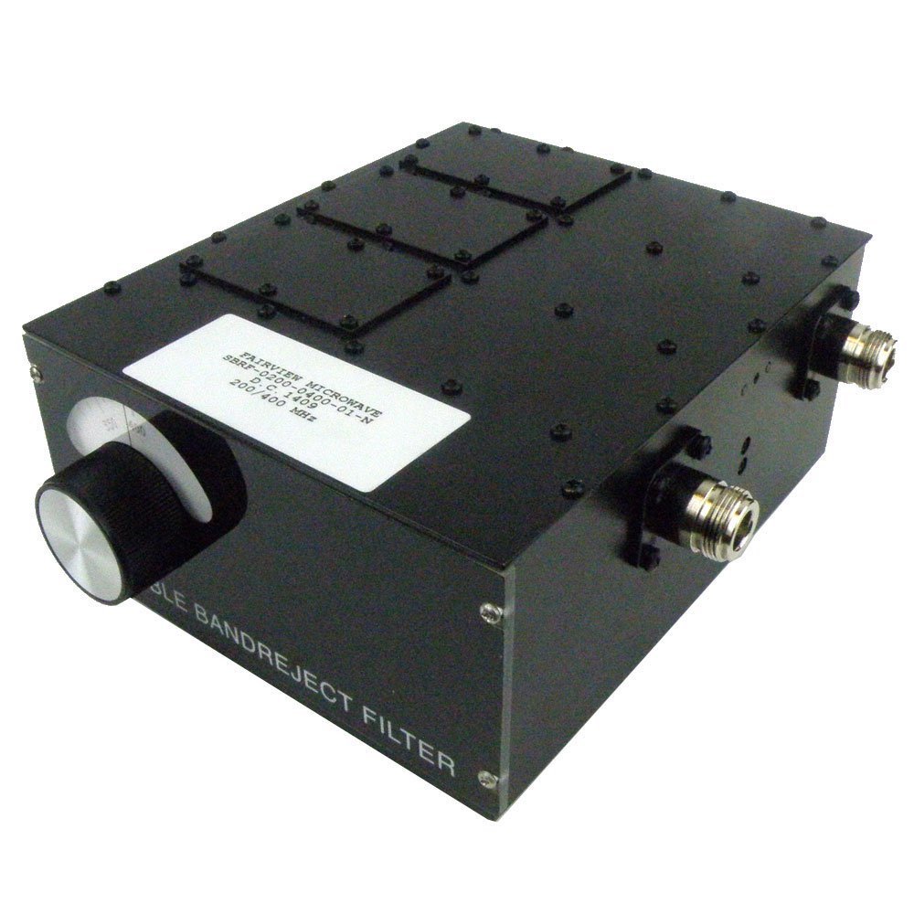
Tunable Band Reject Filter with N Female Interface from 200 MHz to 400
Nevertheless, the block diagram and the response of our idealised band-reject filter are shown in Figures 9 and 10, below. Step 3: Sweeping The Filter. Figure 9: [top] An idealised band-reject filter. Figure 10: [middle] The response of our ideal band-reject filter. Figure 11: [bottom] Controlling a filter by applying an external voltage to a.

Band Stop Filter Band Reject Filter Explained Analysis Simulation
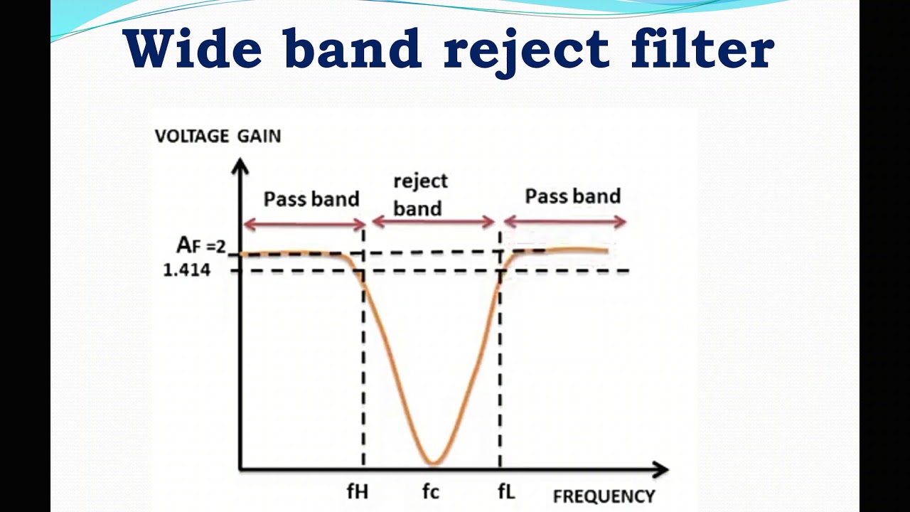
Band stop filters are generally classified as: Wide band stop filter; Narrow band stop filters; The narrow band-reject filters are sometimes referred to as notch filters due to the fact that these possess high-value quality factor i.e., Q more than 10 where the bandwidth is very small in comparison to wide band reject filters.
Module5 Opamp Circuits Band Reject Filter and Problems YouTube
In signal processing, a band-stop filter or band-rejection filter is a filter that passes most frequencies unaltered, but attenuates those in a specific range to very low levels. [1] It is the opposite of a band-pass filter. A notch filter is a band-stop filter with a narrow stopband (high Q factor ).
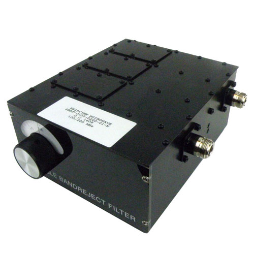
Tunable Band Reject Filter With N Female Connectors From 100 MHz to 200
RLC circuits are normally analyzed as filters, and there are two RLC circuits that can be specifically designed to have a band-stop filter transfer function. These circuits are simple to design and analyze with Ohm's law and Kirchhoff's laws. Band-stop filters work just like their optical analogues. RLC circuits are so ubiquitous in analog.

PPT Frequency Response & Resonant Circuits PowerPoint Presentation
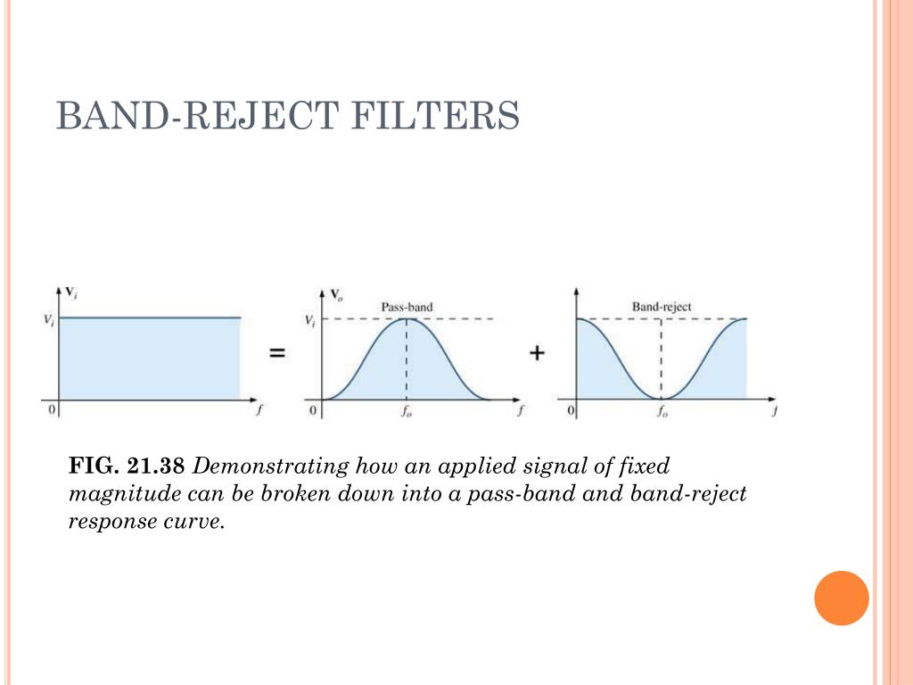
When a band-pass response is needed, you can use a high-pass filter followed by a low-pass filter. When a band-reject response is needed, you can use a summation stage to add a low-pass-filtered signal to a high-pass-filtered signal. The cutoff frequencies of the two filters are adjusted such that the frequency responses overlap in a way that.
PPT Frequency Response & Resonant Circuits PowerPoint Presentation
Full line of customizable Band Reject Filters of varying frequencies, bandwidths and Q requirements. Available in various topologies - MPG
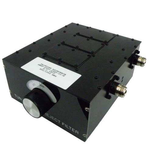
Tunable Band Reject Filter With N Female Connectors From 500 MHz to
The band stop filter, also known as a band reject filter, passes all frequencies with the exception of those within a specified stop band which are greatly attenuated.

Band Reject Filter Band Stop Filter Design and Simulation using
By summing the high-pass and low-pass outputs of the state-variable filter, a notch, or band-reject, filter may be formed. Filters of this type are commonly used to remove interference signals. The summation is easily performed with a simple parallel-parallel summing amplifier, as shown in Figure 11.8.1. Figure 11.8.1: Notch filter.

88108 MHZ BandReject (Notch) Filter
Band Reject Filters are available as narrowband filters or wideband filters, supporting bandwidths from 1% to 200%, in configurations of 3 to 8 sections. Subscribe to receive all MPG updates. Salisbury, MD 21801, [email protected] Band Reject Filter frequency: VHF and UHF from 800 KHz to 18 GHz (L band, S band, C band, X band, Ku band)

Band Reject Filter OR Band Elimination Filter Electrical Revolution
If the filter is wideband, it is referred to as a band-reject filter and if the filter is narrow-band, it is referred to as a notch filter. The characteristics of a band-stop filter are exactly the reverse of the bandpass filter. Hence, the notch filter is a complement of the bandpass filter.
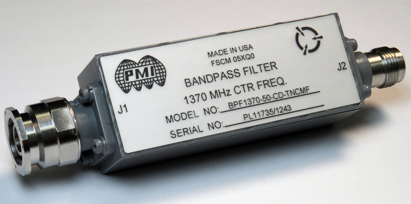
Bandpass Filter and Band Reject Filter
All Band Reject Filters or Band Stop Filters made by Microwave Products Group, including Notch Filters, are available as a wideband or narrowband reject filter and can be customized to user specifications. For example, Notch Filters are most commonly applied to applications where it is necessary to attenuate a single frequency. However.
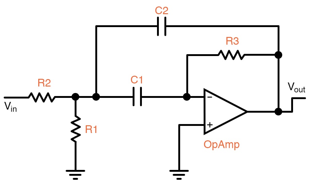
OpAmps as Active BandPass and Active BandReject Filters Video Tutorial
Filters are networks that process signals in a frequency-dependent manner. The basic concept of a filter can be explained by examining the frequency dependent nature of the impedance of capacitors and inductors. Consider a voltage divider where the shunt leg is a reactive impedance.
Band Rejection Filter SYM Technology
A band stop filter is a device that enables the passage of various frequencies but rejects particular ones. Due to this feature, it is also called a band elimination filter or notch filter (Circuits Today, Band Stop Filter, 2011). The device is designed in a manner that allows the frequencies to pass above and below a particular range.
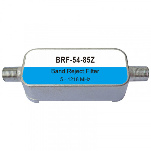
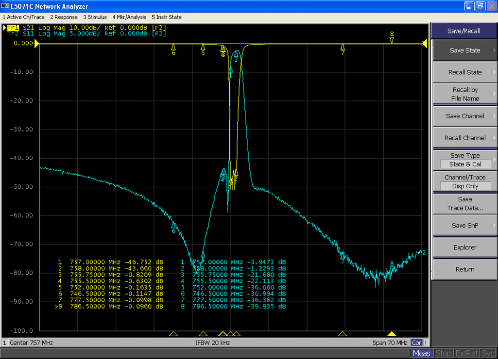
BRF5485Z Band Reject Filter
The band reject filter is also called a band stop or band elimination filter because it eliminates a certain band of frequencies. Wide Band Reject Filter: Figure 15.20 (a) shows wide band reject filter circuit using a low pass filter, a high pass filter and a summing amplifier.